Product Origin:
ChinaItem NO.:
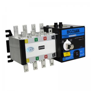
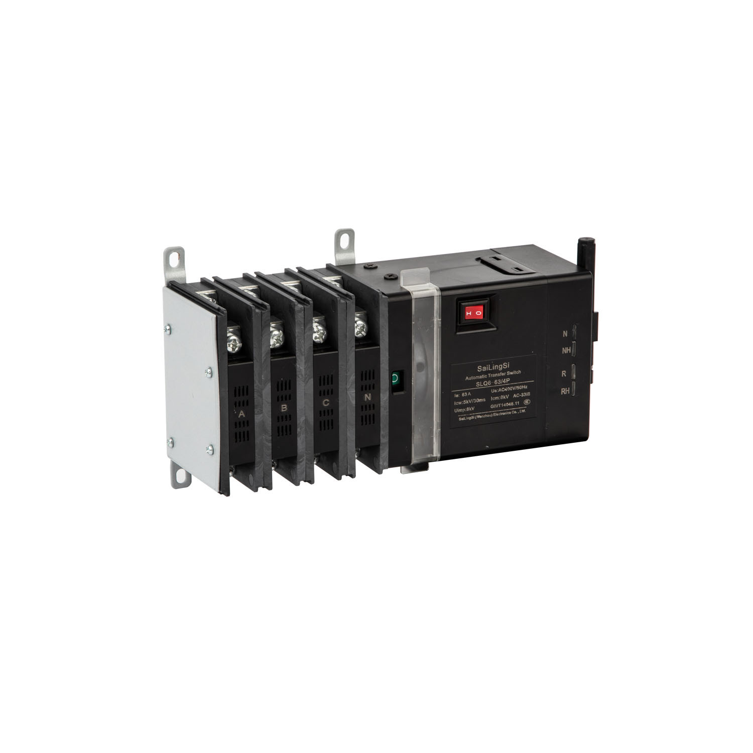
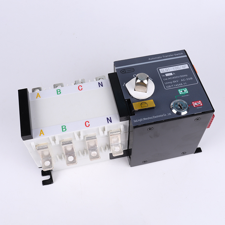
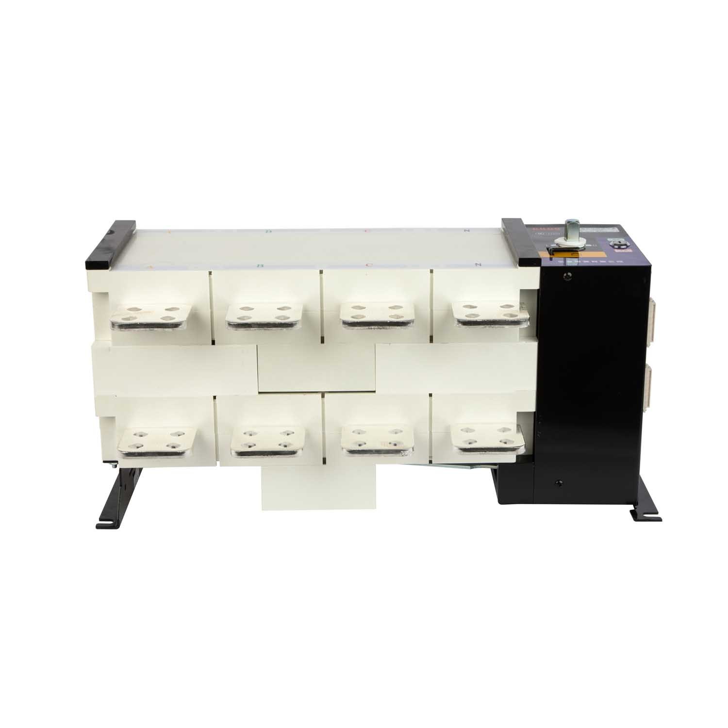
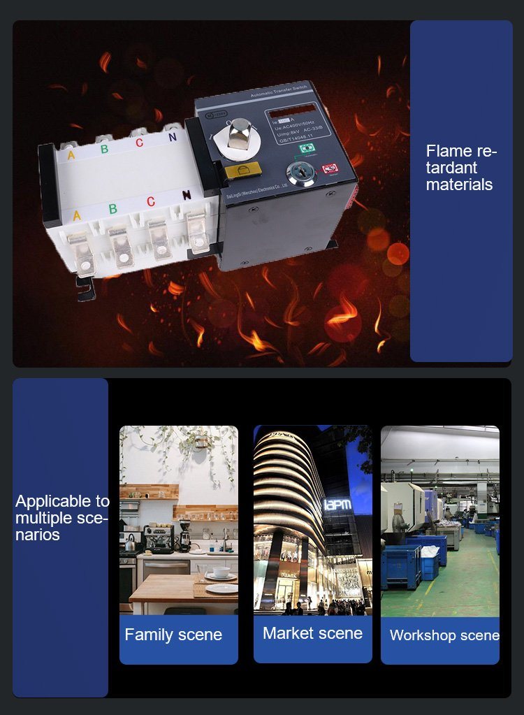
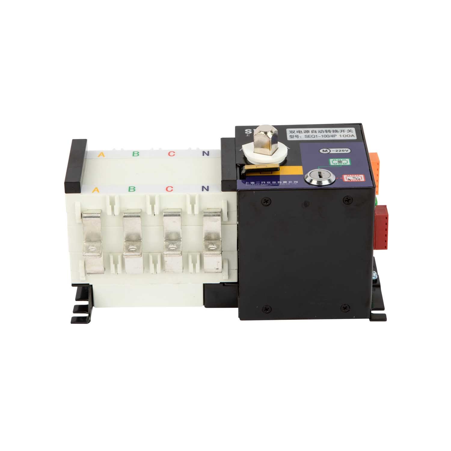
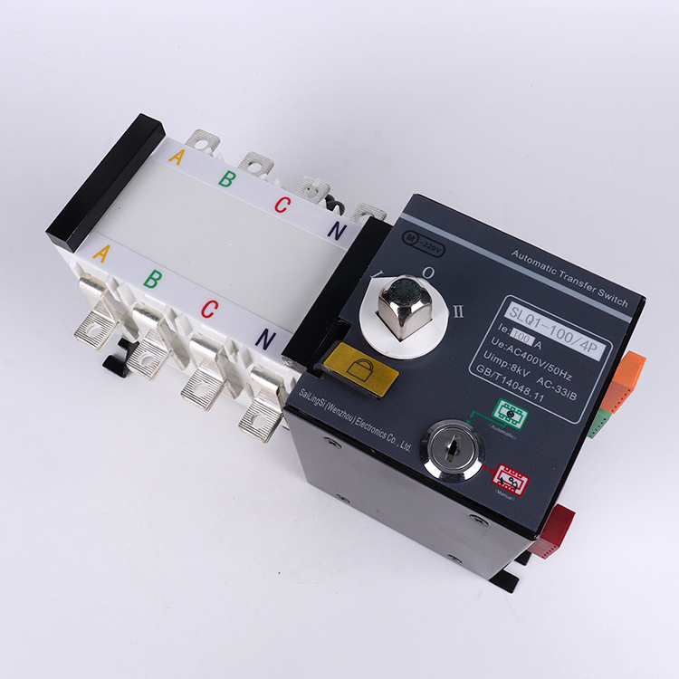
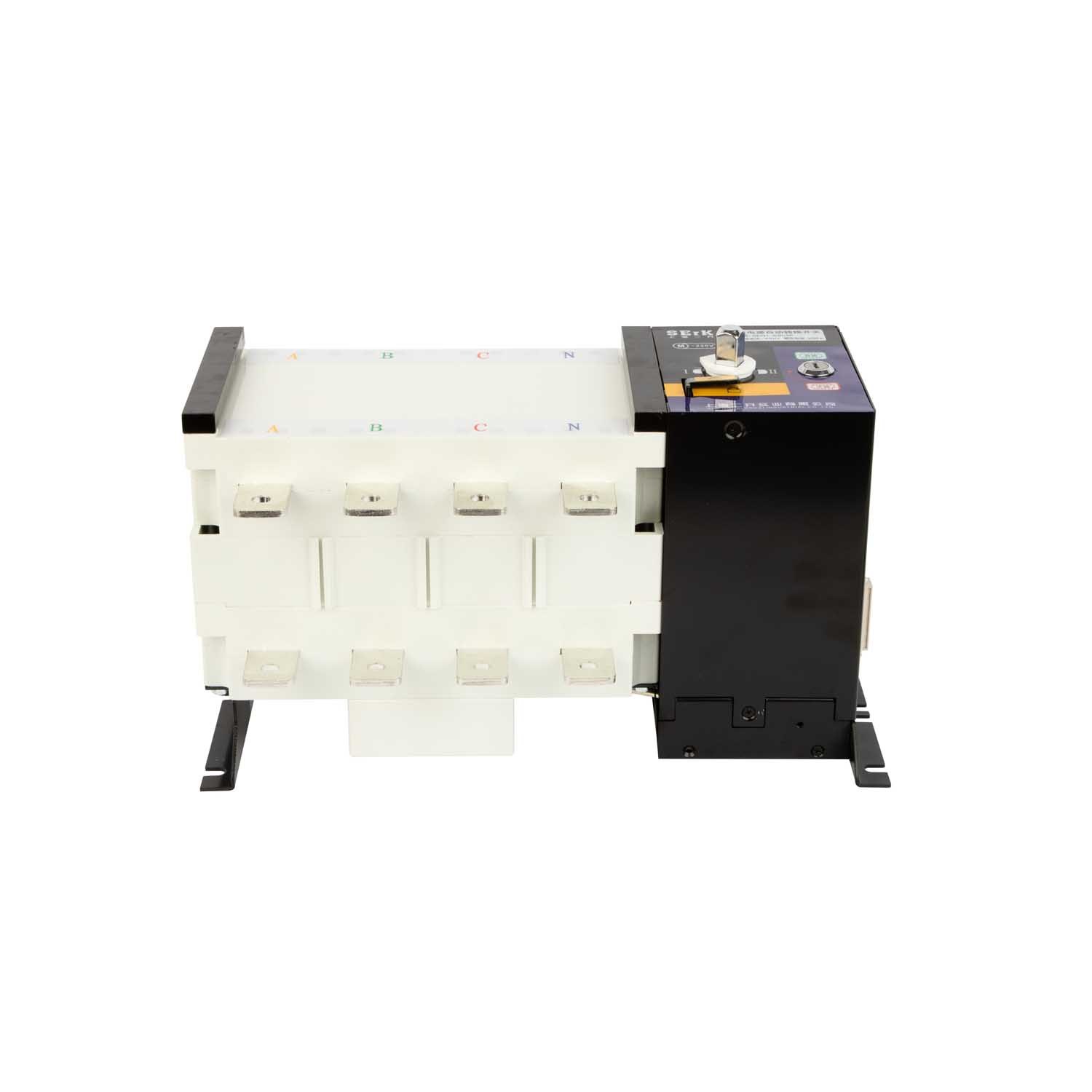
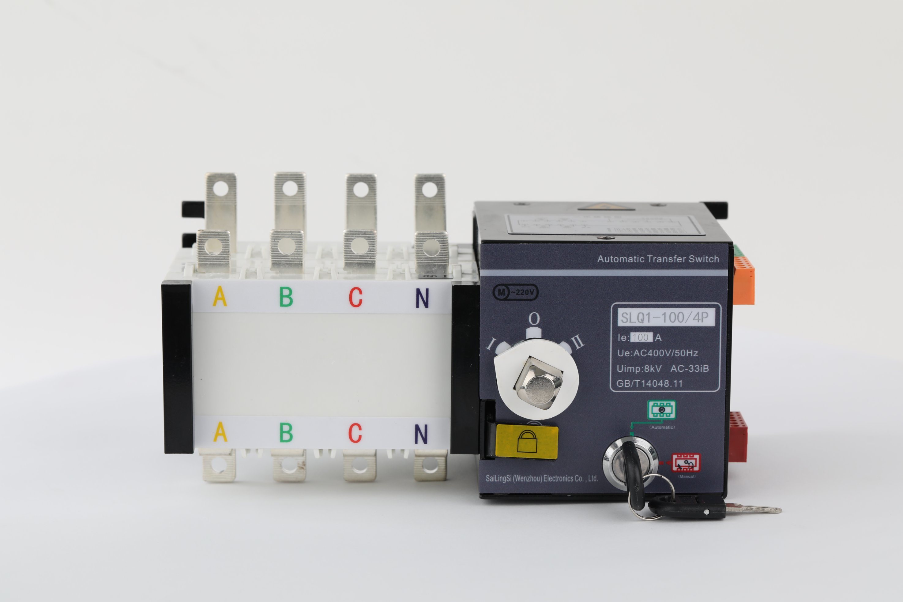
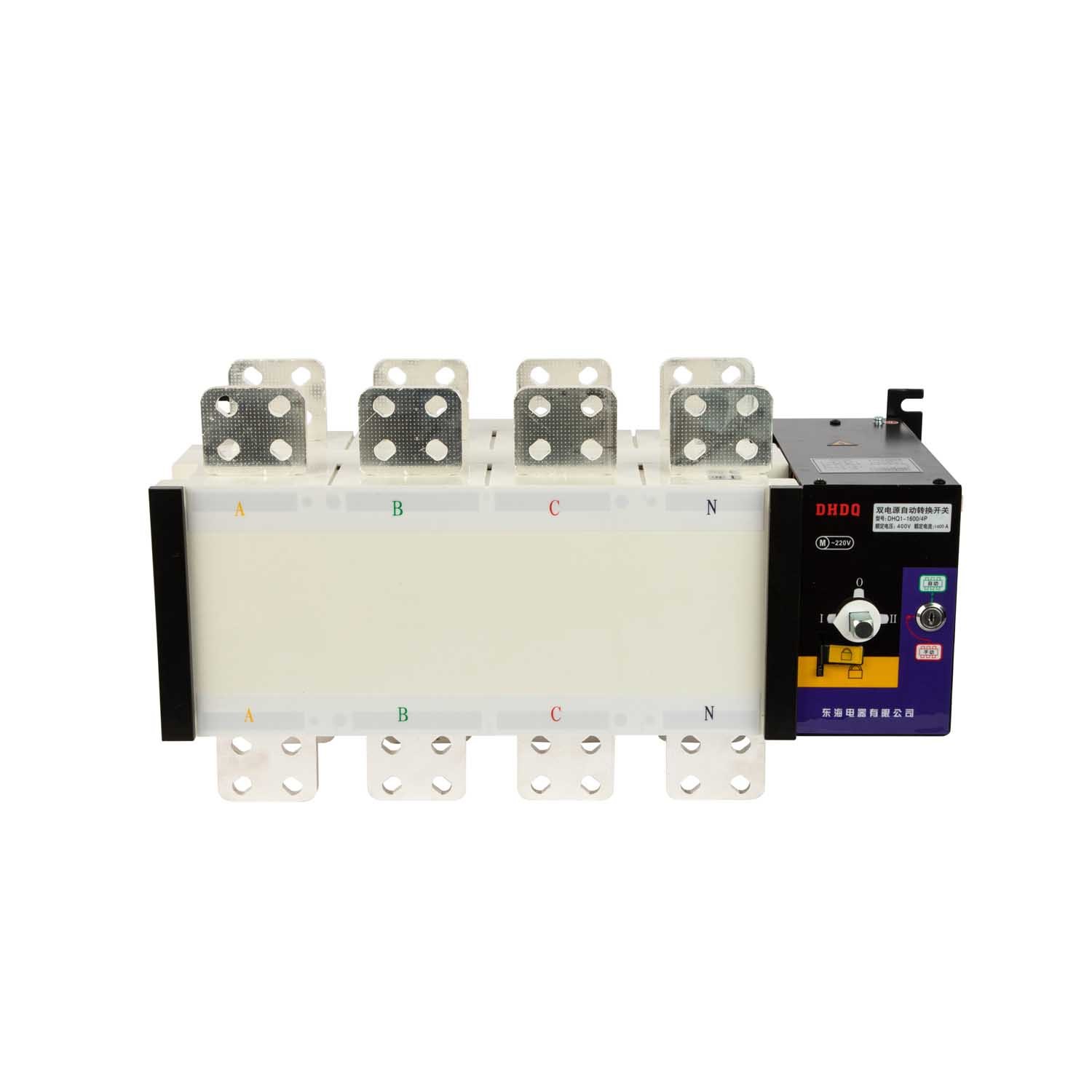
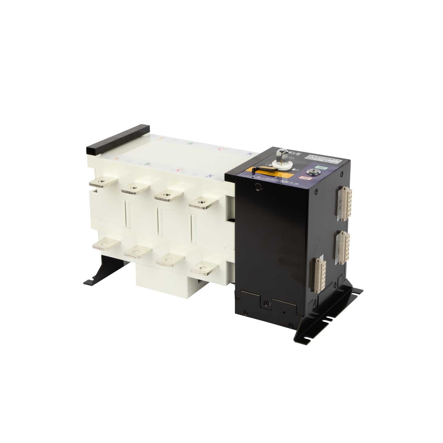
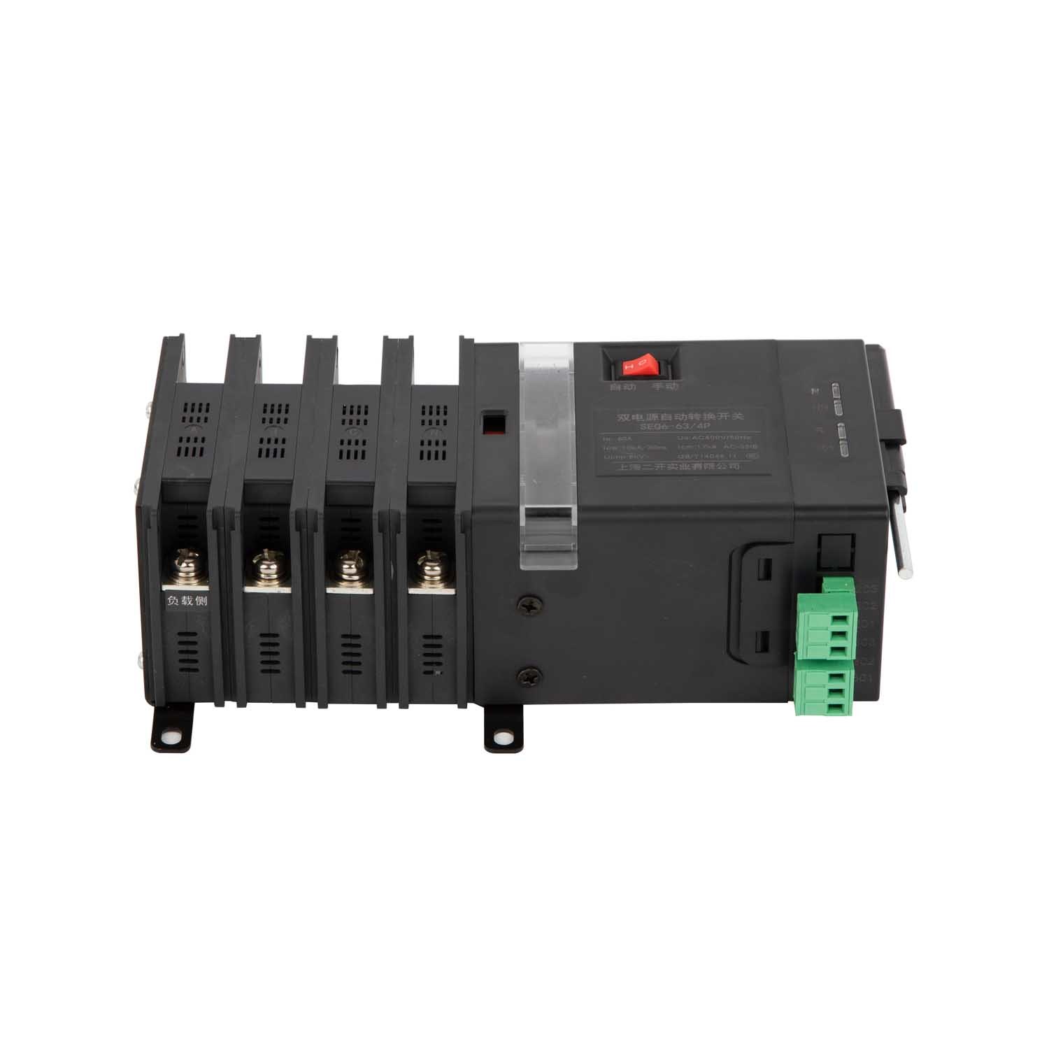
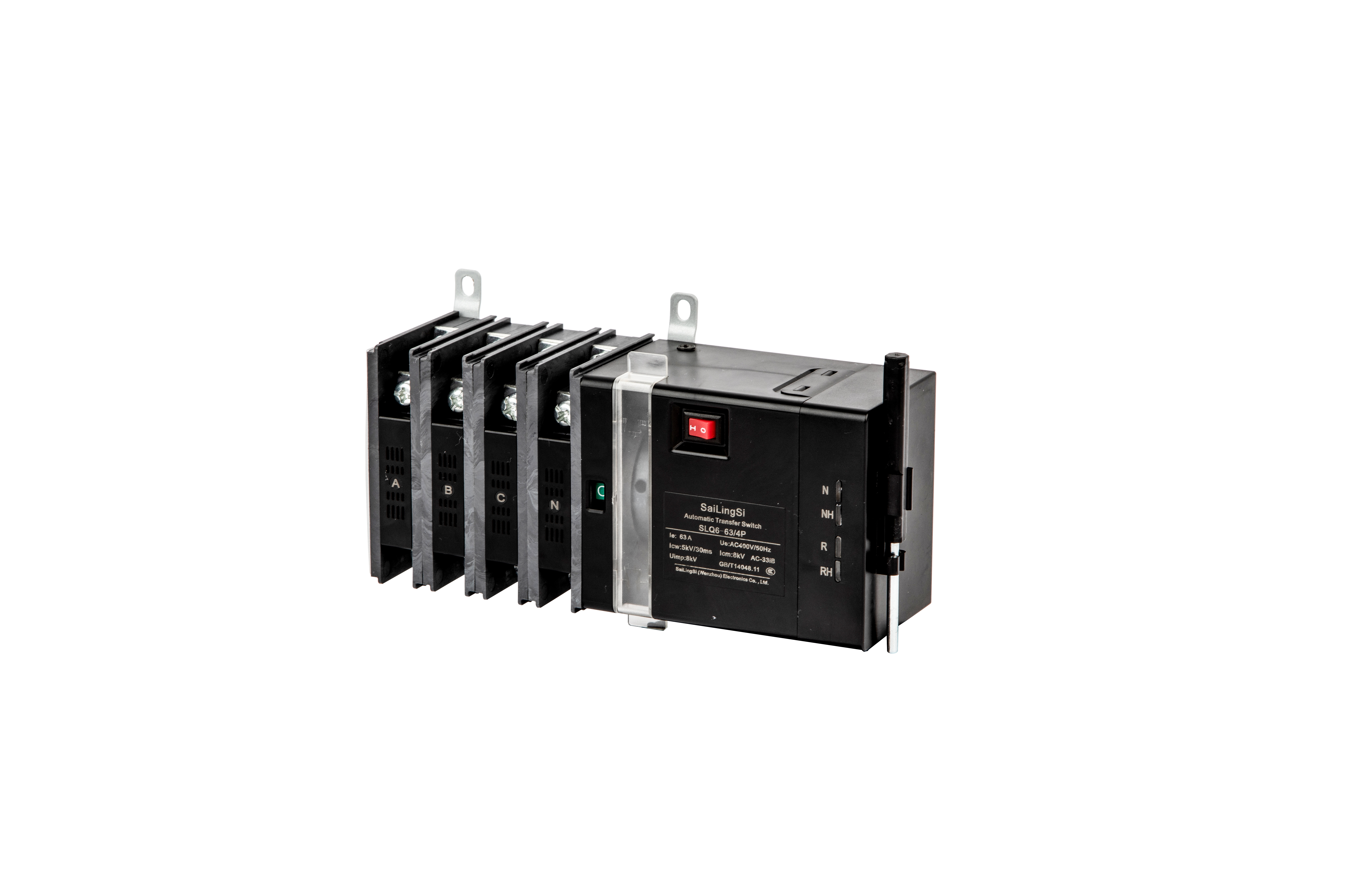
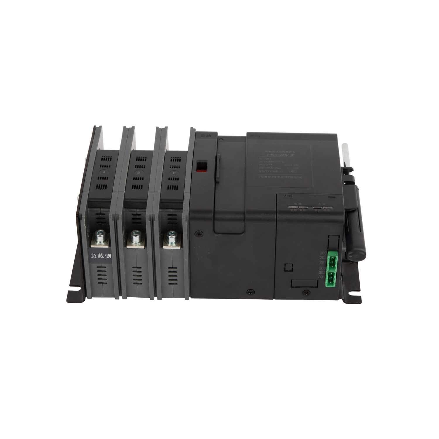
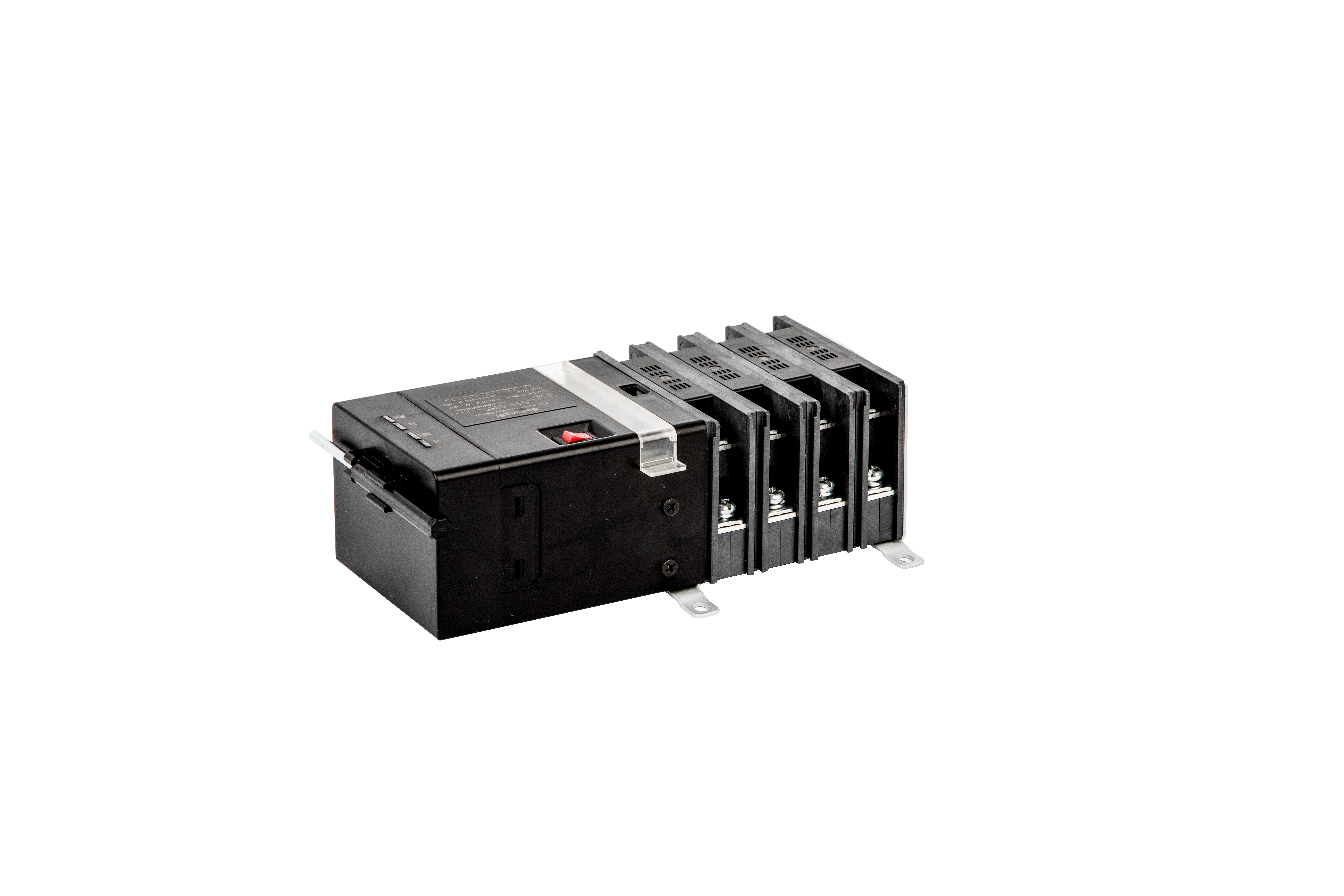
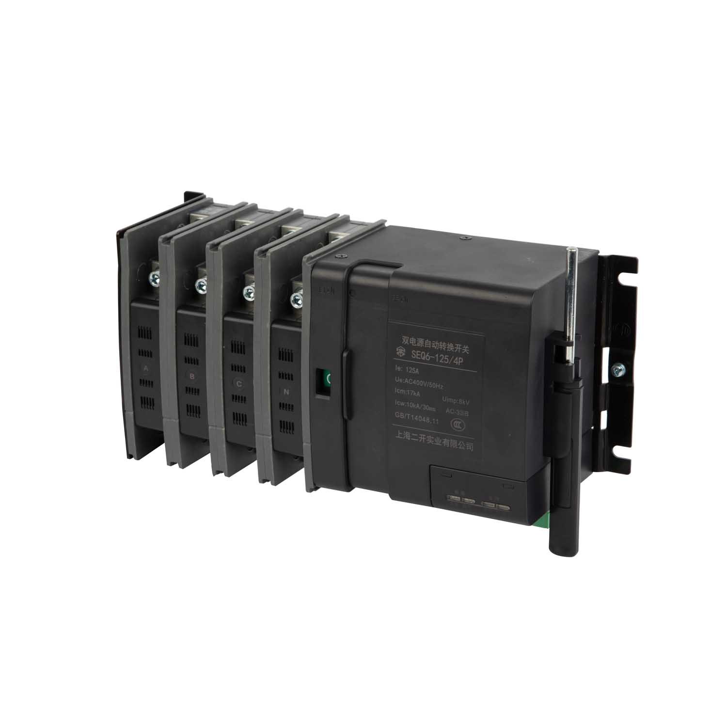
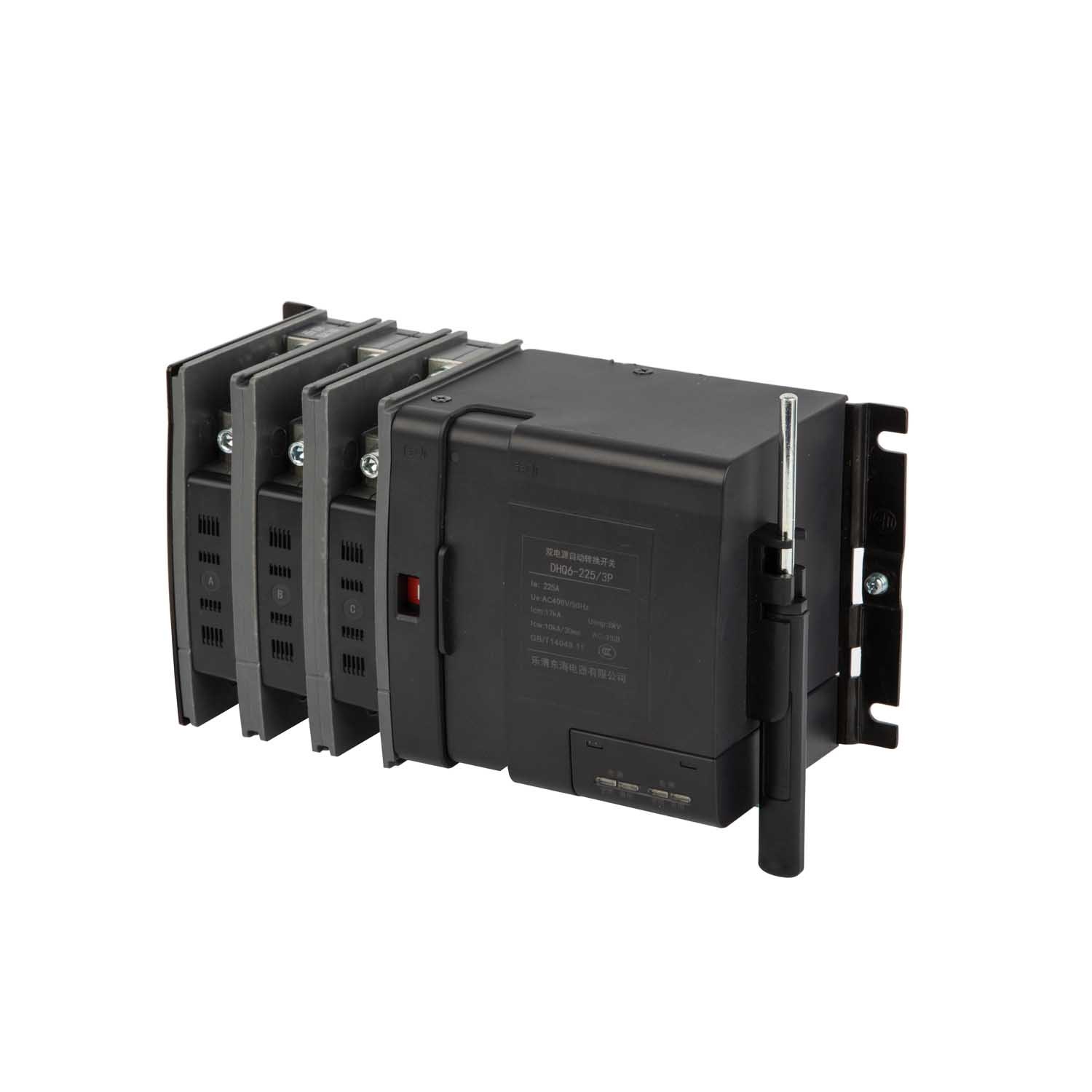
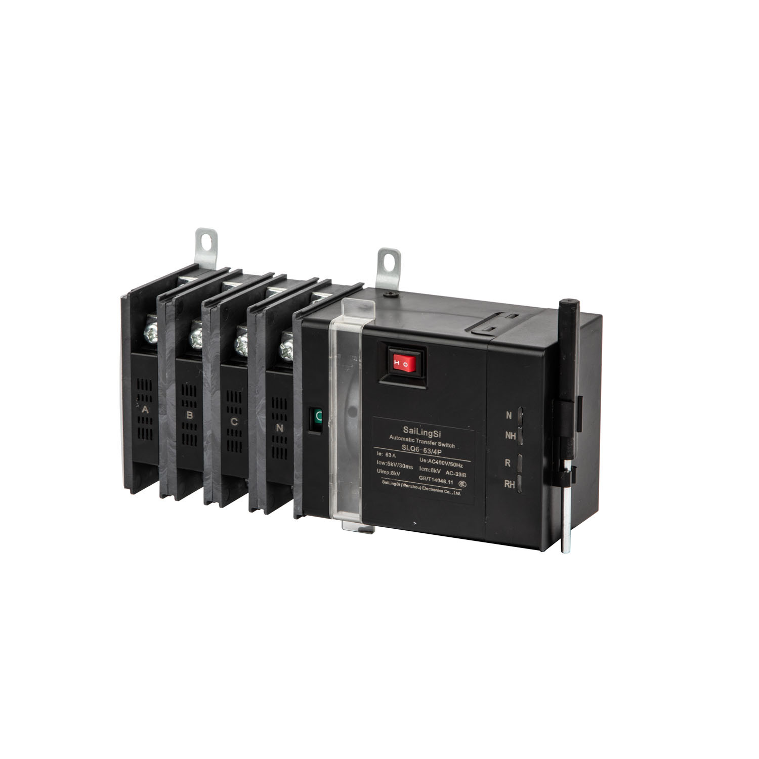
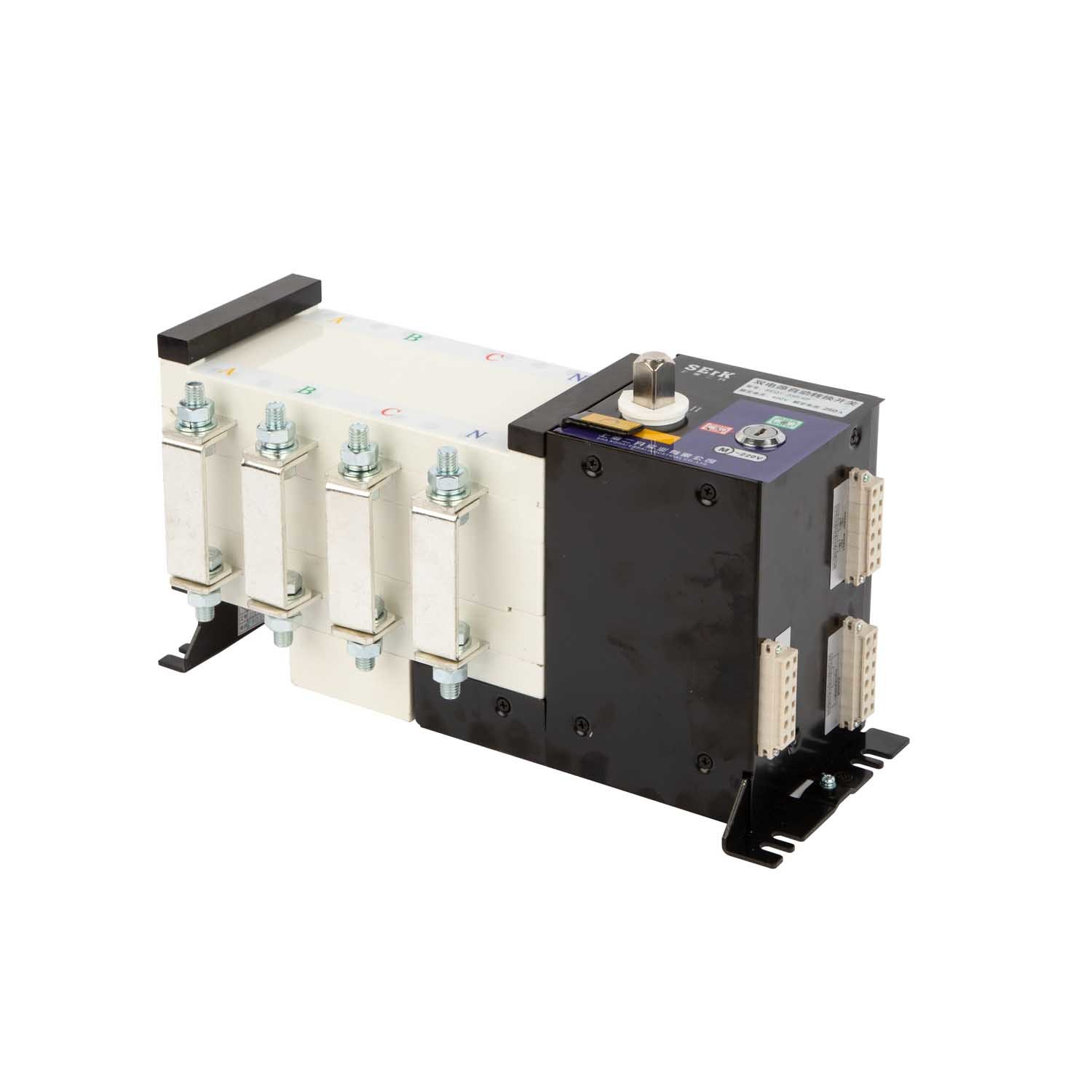
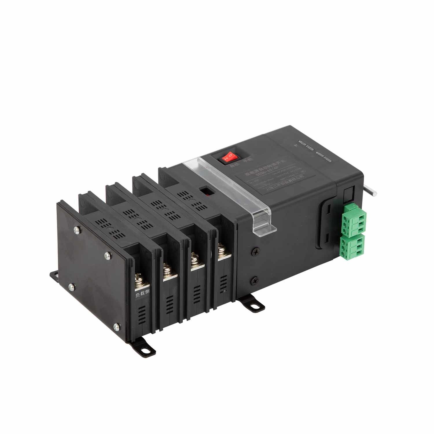
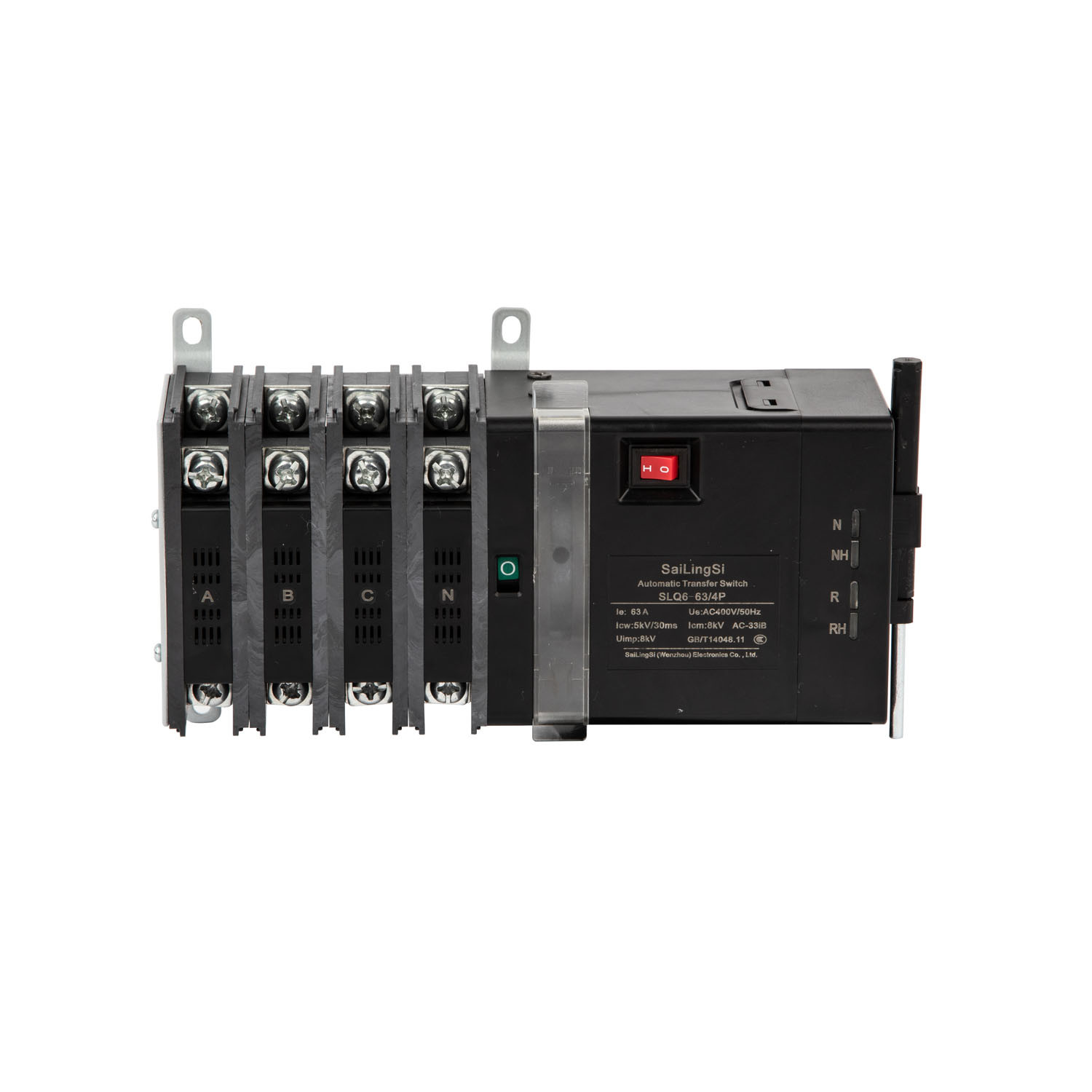
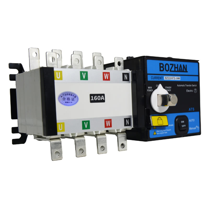
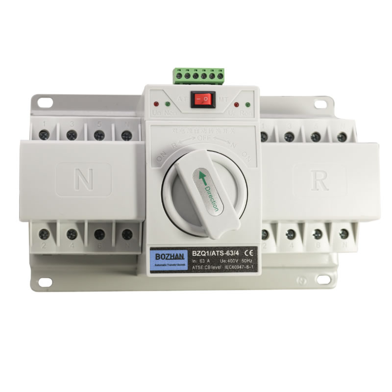
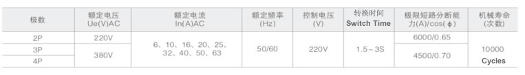
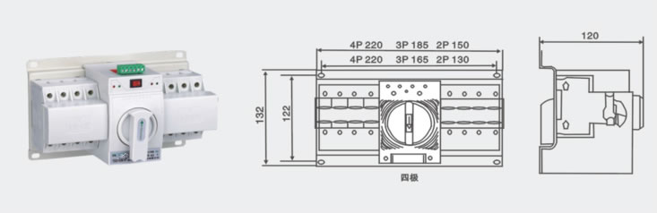
ATS Q1 DUAL POWER AUTOMATIC TRANSFER SWITCH1 It has small volume and simple structure; convenient operation, long service life, 2P, 3P, 4P can be provided:
2 The switching driver uses a single motor driver, smooth, noise, and small impact:
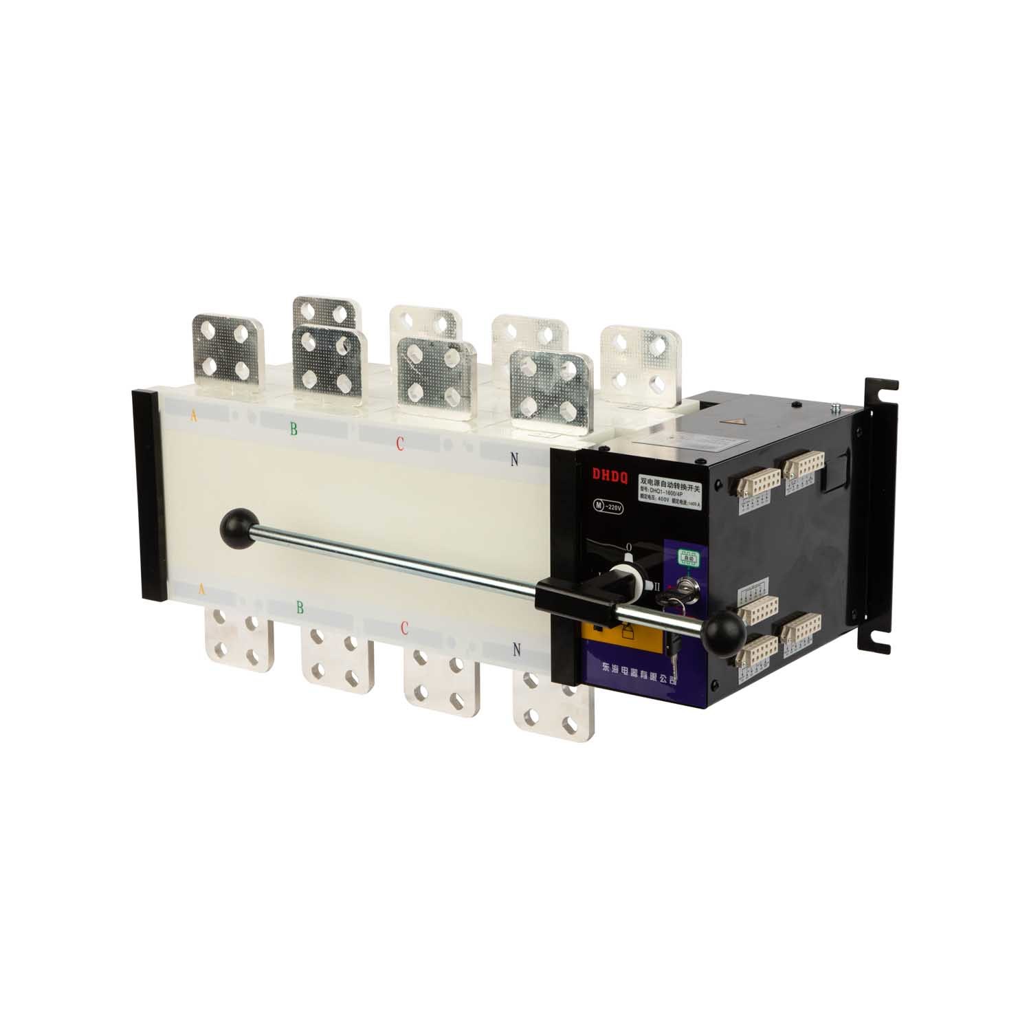
3 Have mechanical chain and electrical links, reliable switching, manual and automatic switching can be
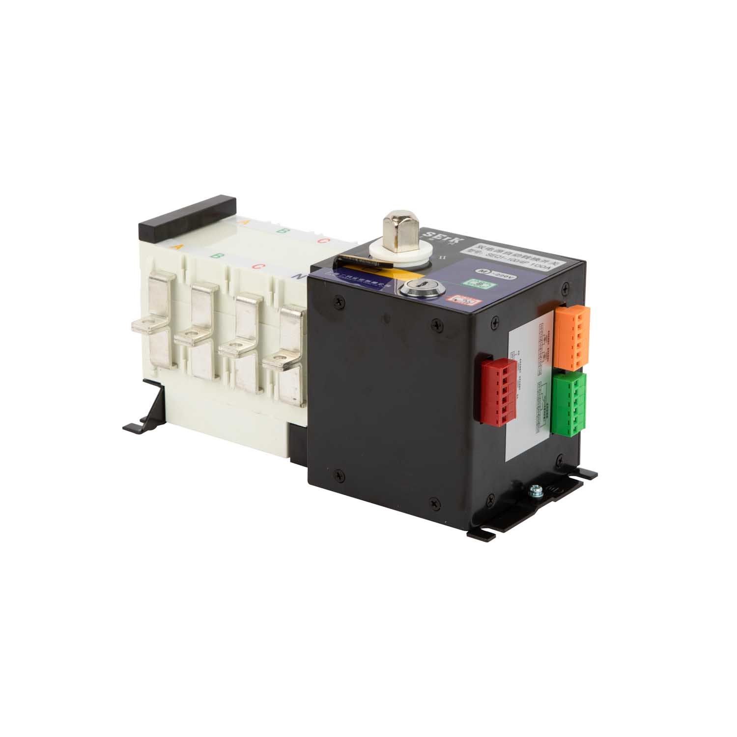
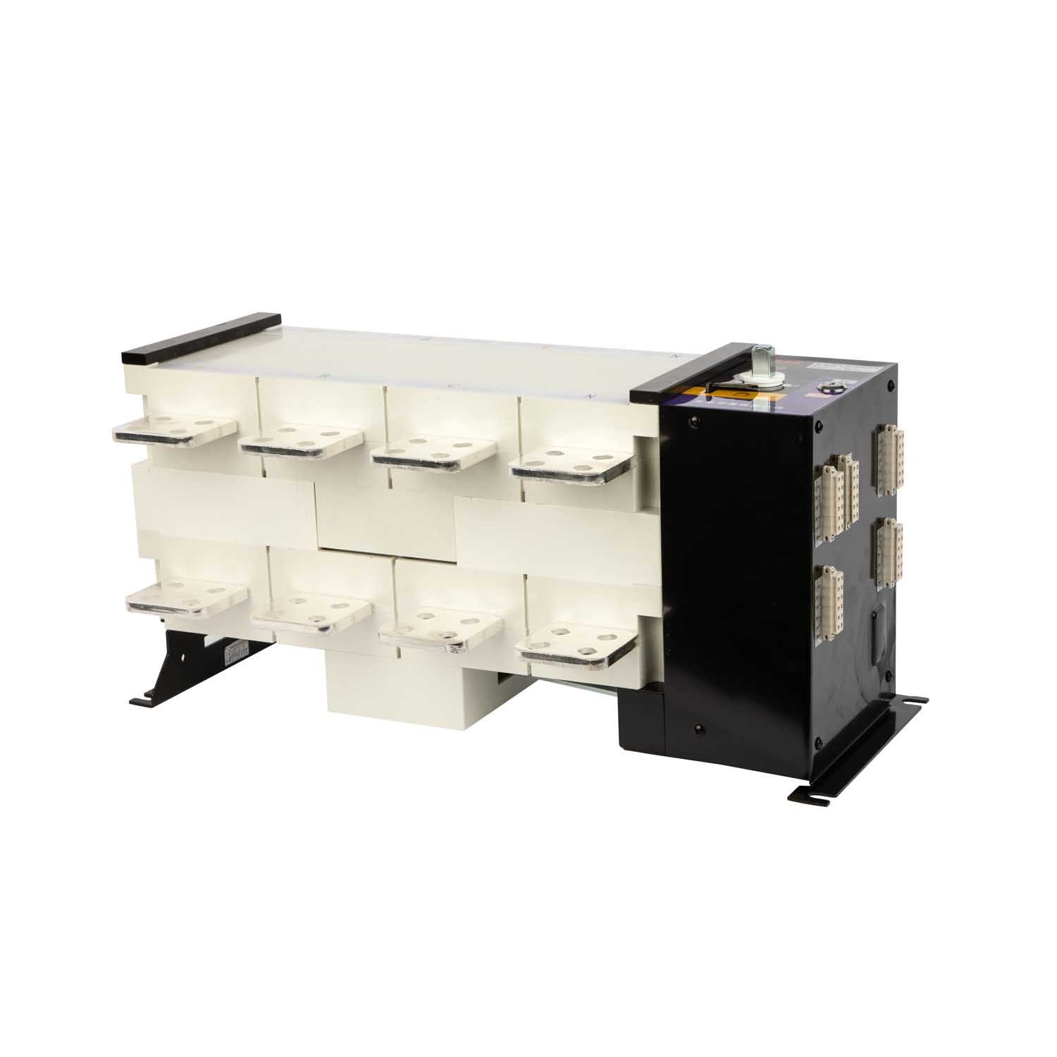
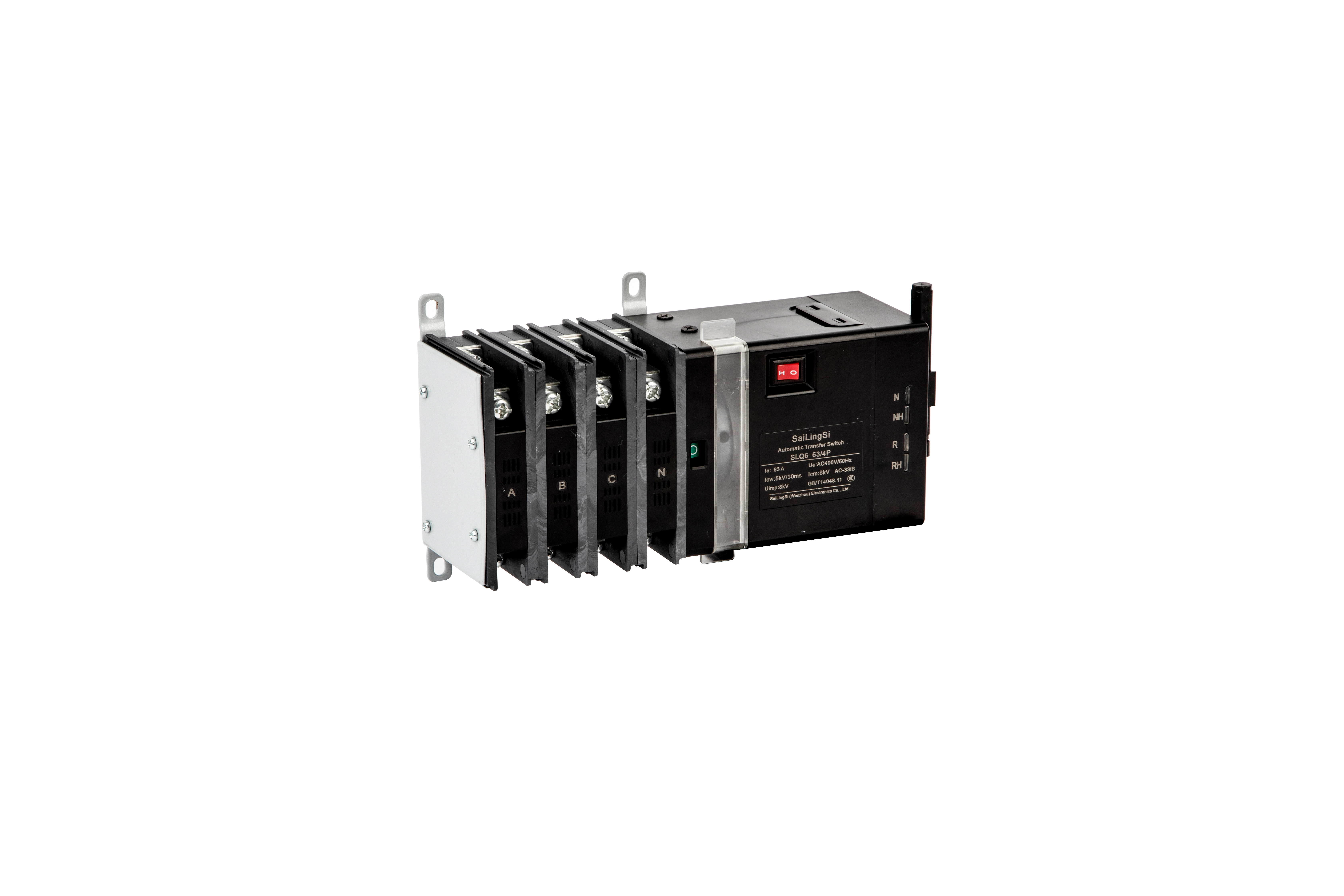
4 Commonly used, spare circuit breaker rated current can be different
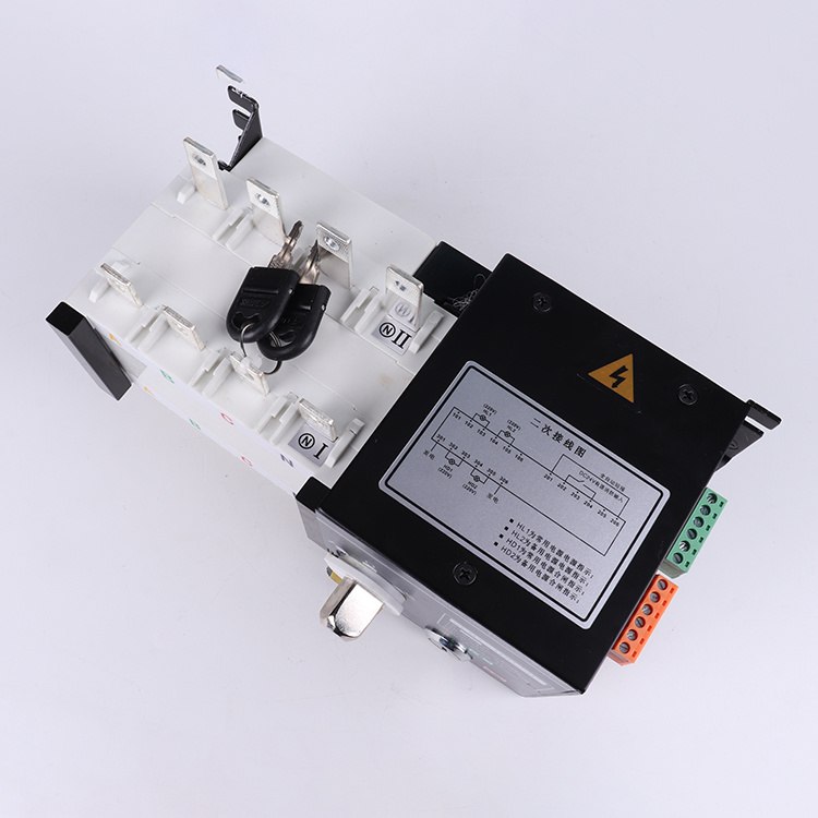
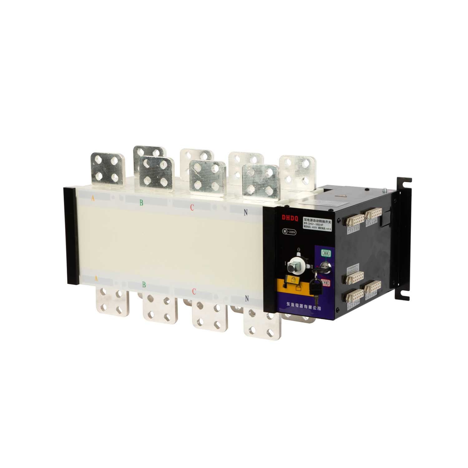
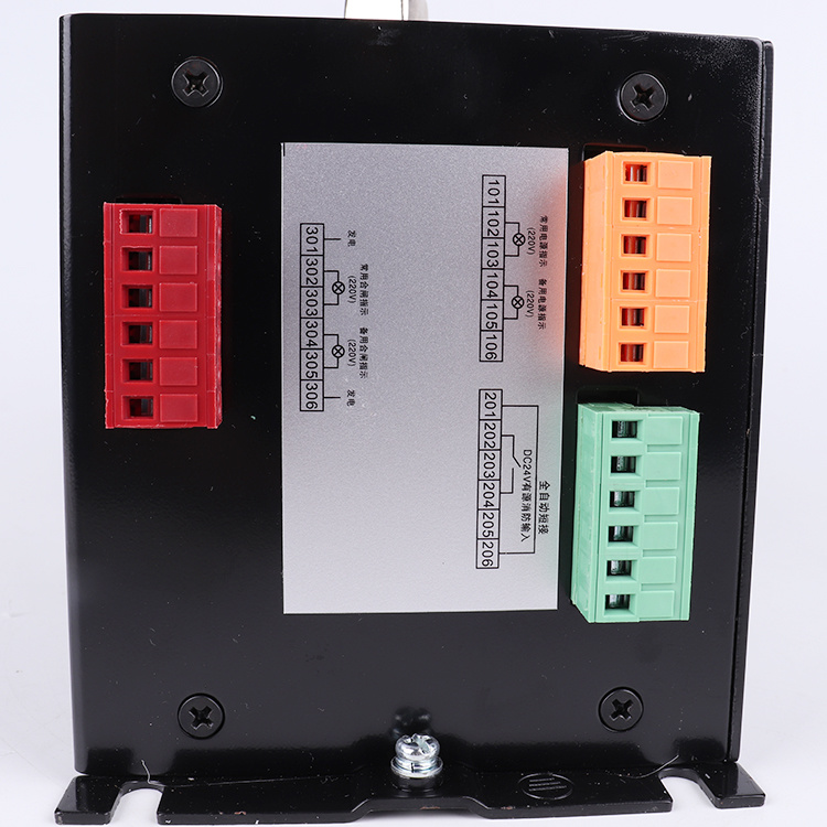
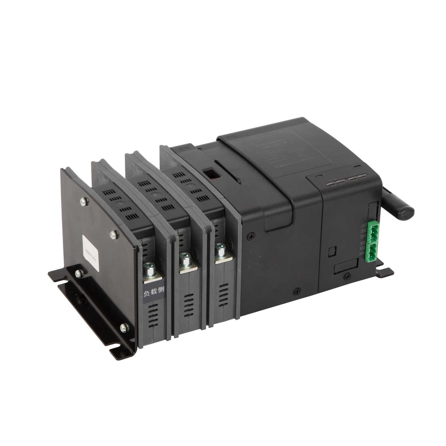
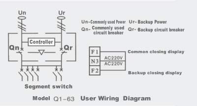
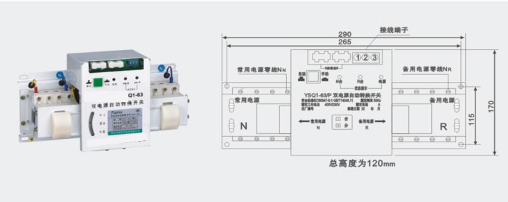
5 A.T.S interior has a wiring terminal supply user wiring that can reflect various instructions on the circuit breaker (open or closed) status of the ATS panel.
Note: According to the diagram, select wires with appropriate loading to connect the incoming and outgoing wires of the two miniature circuit breakers, and the phase sequence of the incoming wires must be consistent. Three-pole miniature circuit breaker
From the neutral line to the neutral line N terminal of the device, otherwise the ATS cannot work normally.
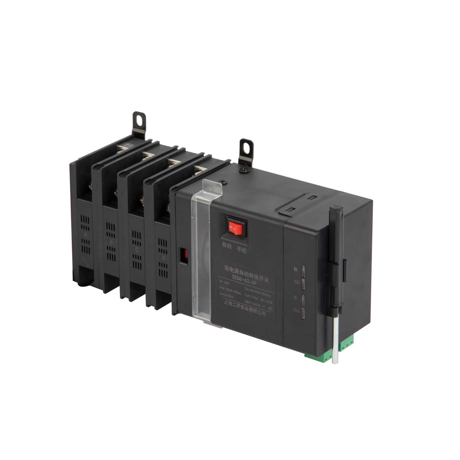
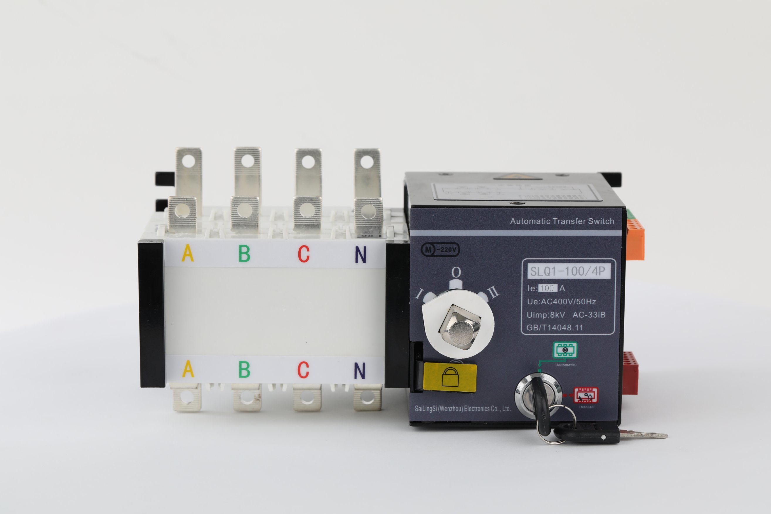
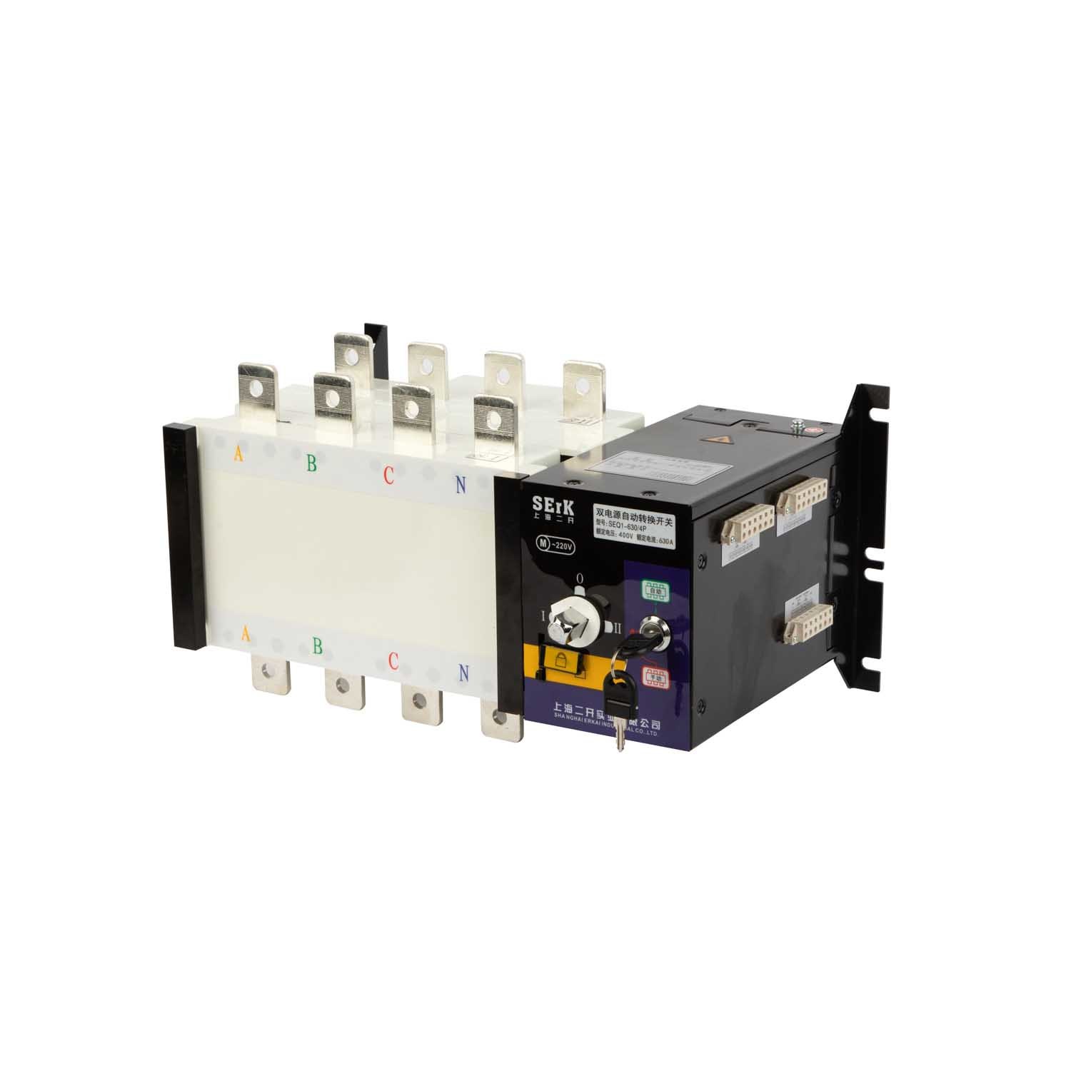
Regardless of whether the normal power supply and the backup power supply have voltage, manual operation can be adopted. When operating manually, the manual-automatic button should be placed in the manual position, when pushed
When the handle is turned clockwise to the terminal, the backup power supply executes the opening of the circuit breaker Qr, and the common power supply executes the closing of the circuit breaker Qn: when the handle is pushed counterclockwise to the terminal, the backup power supply
The source executes the closing of the circuit breaker Qr, and the normal power executes the opening of the circuit breaker Qn:
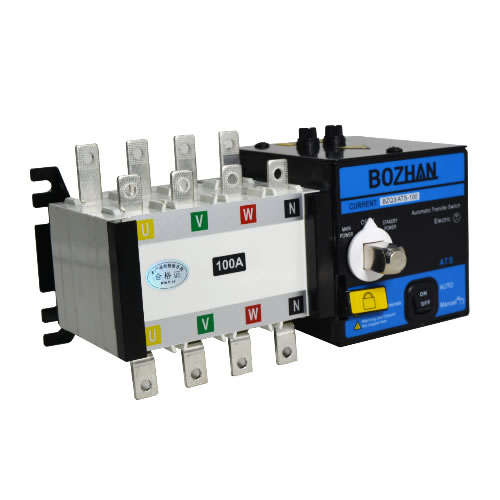
Set the manual-automatic button to the automatic position. If the common power supply is normal, the transfer switch will switch to the common power supply, and the common power indicator light on the panel will be on:
If the common power supply is abnormal. Then the transfer switch will switch to the backup power supply, and the backup power indicator light in the panel will be on.
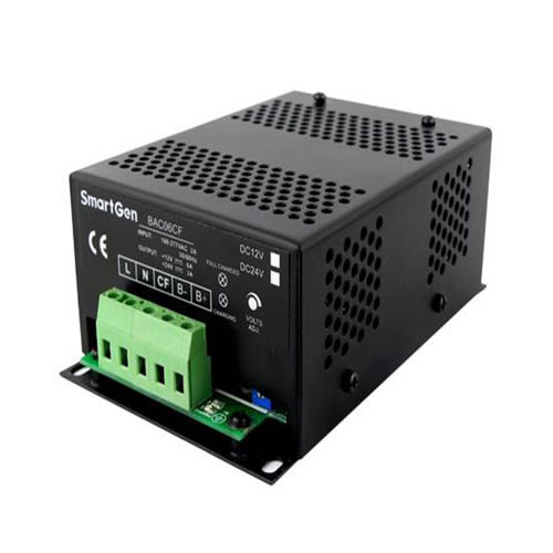
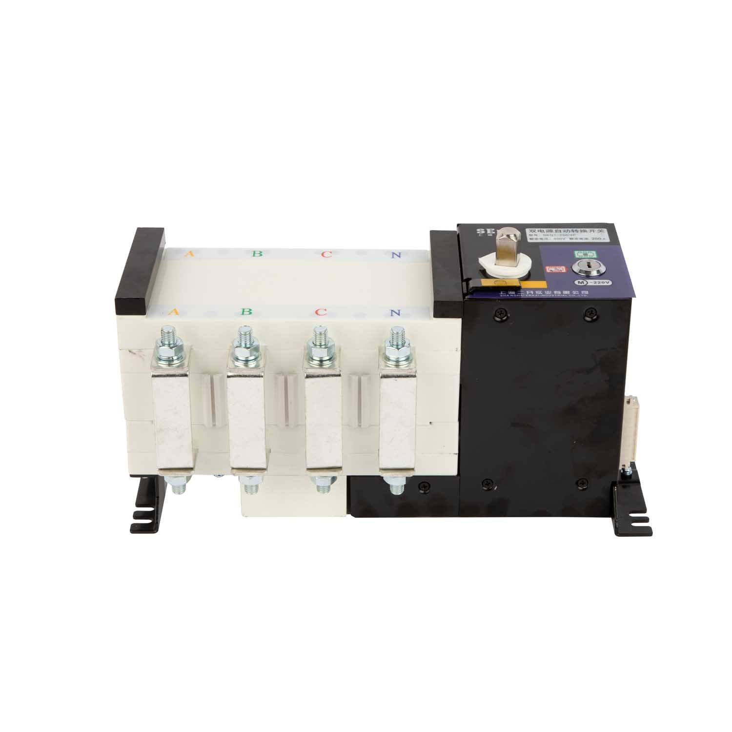
The transfer switch is equipped with two 1A fuses and a terminal. The fuse is used for short-circuit protection of the automatic controller, and the terminal is used to connect the indicator light to the control.
The panel of the box provides an active power supply, and its voltage is AC 220V. For specific operations, please refer to the wiring diagram in the accompanying manual for connection.
When the power supply changes under the automatic control state, the electric operating mechanism does not operate, that is, the small circuit breaker cannot be closed or opened. At this time, you should first check (1) whether the power grid is powered off: (2) whether the wiring is disconnected;
(3) Whether the fuse of the product itself is blown. If there is power at the front of any circuit breaker, the wiring is correct, and the fuse is intact, it still cannot be closed or opened. At this time, please ask a professional to repair or contact the manufacturer to solve the problem.
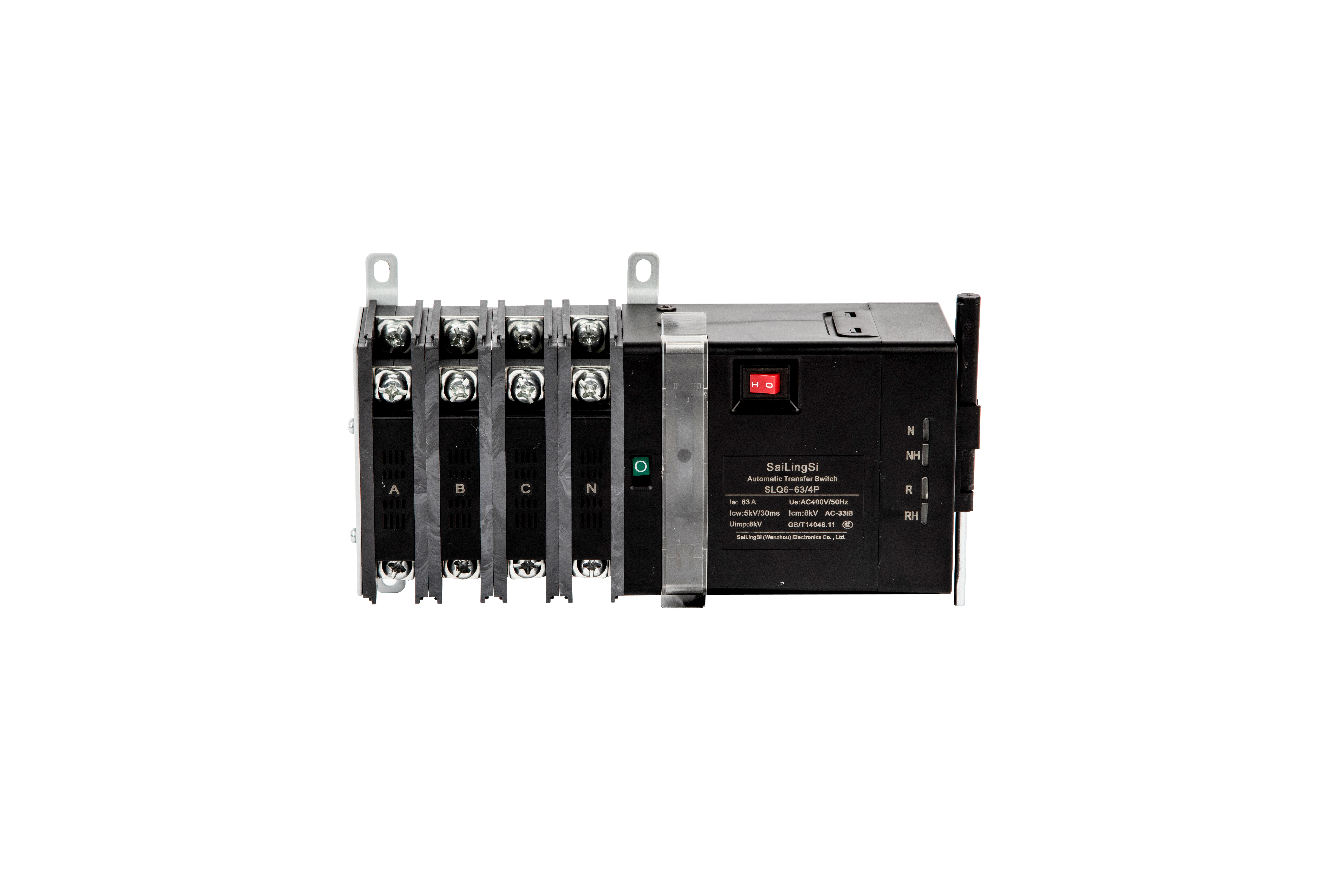
When ordering, the user should indicate the model and specification of the device, and the model, specification and number of poles of the new circuit breaker. If you order to turn off the switch automatically, switch type, automatic switch and automatic reset
Type, rated current is 63A, four poles, that is written as: BZO1-63/4P63A.
If the user has special requirements, please contact the manufacturer and explain it when ordering.
If you have inquiry, please leave us a message, we will reply you as soon as we can!


 pt
pt ar
ar ko
ko